Source:
- https://beyondlogic.org/usbnutshell/
- https://www.weigu.lu/microcontroller/avr_usb_libs/index.html
- https://www.usb.org/document-library/usb-20-specification
- https://learn.microsoft.com/en-us/windows-hardware/drivers/usbcon/usb-control-transfer
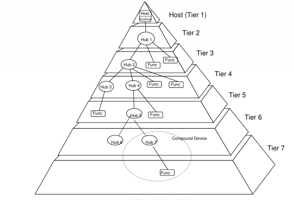
Bus Topology
The USB connects USB devices with the USB host. The USB physical interconnect is a tiered start topology. A hub is at the center of each star. Each wire segment is a point-to-point connection between the host and a hub or function, or a hub connected to another hub or function:
Electrical
The USB transfers signal and power over a four-wire cable:
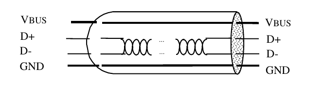
VBus (nominally 5 V) and GND wires deliver power to devices. D
There are 3 data rates:
- high-speed signaling bit rate is 480 Mb/s
- full-speed signaling bit rate is 12 Mb/s
- low-speed signaling bit rate at 1.5 Mb/s.
The clock is transmitted, encoded along with the differential data. The clock encoding scheme is NRZI (No Return to Zero Invert on Ones) with bit stuffing to ensure adequate transitions.
A SYNC field preceeds each packet to allow the receiver(s) to synchronize their bit recovery clocks.
In order to provide guaranteed input voltate levels and proper termination impedance, biased terminations are used at each end of the cable.
Bus Protocol
The USB is a polled bus. The Host Controller initiates all data transfers.
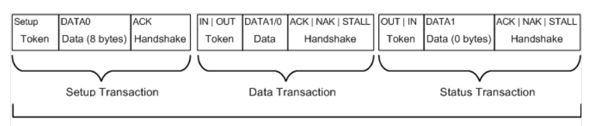
Most bus transactions involve the transmission of up to three data packets.
Each transaction begins when the Host Controller, on a scheduled basis, sends a USB packet describing the type and direction of transaction, the USB device address, and endpoint number. This packet is referred to as the “token packet”. The USB device that is addressed selects itself by decoding the appropriate address fields.
In a given transaction, data is transferred either from the host to a device or from a device to the host. The direction of data transfer is specified in the token packet. The source of the transaction then sends a data packet or indicates it has no data to transfer.
The destination, in general, responds with a handshake packet indicating whether the transfer was successfull.
Bus enumeration
Bus enumeration is activity that identifies and assigns unique address to devices attached to a bus. Because the USB allows USB devices to attach or detach from the USB at any time, bus enumeration is an on-going activity for the USB system software. Additionally, bus enumeration for the USB also includes the detection and processing of removals.
USB Packet fields
Each USB transaction consists of a
- token packet (== header defining what it expects to follow)
- optional data packet (containing payload)
- status packet (used to acknowledge transactions and to provide a means of error detection)
Data on the USB bus are transmitted LSB bit first. Usb packets consists of the following fields:
- Sync
All packets must start with a sync field. The sync field is 8 bits long at low and full speed, or 32 bits long for high speed and is used to synchronise the clock of the receiver with that of the transmitter. The last 2 bits indicate where the PID field starts.
- PID
PID stands for Packet ID. This field is used to identify the type of packet that is being sent. The following table shows the possible values:
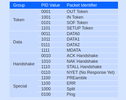
There are 4 bits of the PID, however to insure it is received correctly, the 4 bits are complemented and repeated, making 8 bit PID in total. The resulting format is shown below:
| PID0 | PID1 | PID2 | PID3 | PID0 | PID1 | PID2 | PID3 |
- ADDR
The address field specifies which device the packet is designated for. Being 7 bits in length allows for 127 devices to be supported. Address 0 is not valid, as any device which is not yet assigned an address must respond to packets sent to address zero.
- ENDP
The endpoint field is made up of 4 bits, allowing 16 possible endpoints. Low speed devices, however can only have 2 additional endpoints on top of the default pipe.
- CRC
Cyclyc Reduncancy Checks of the payload data. Token packets have 5 bit CRC, while data packets have 16 CRC.
- EOP
End of packet. Signalled by a Single Ended Zero (SE0) for approximately 2 bit times followed by a J for 1 bit time.
USB Packet types
There are 4 different packet types in USB:
- Token packets
Token packets indicate the type of transaction to follow. There are 3 types of token packets:
- In
Inform the USB device that the host wishes to read information. - Out
Informs the usb devices that the host wishes to send information. - Setup
Used to begin control transfer.
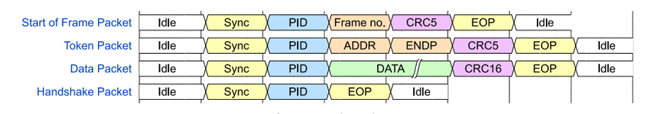
Token packets must conform to the following format:
- In

- Data packets
There are 2 types of data packets each capable of transmitting up to 1024 bytes of data.- DATA0
- DATA1
High speed mode defines another 2 data PIDs: DATA2 and MDATA.
Data packets have the following format:

- Handshake packets
There are 3 types of handshake packets which consists simply of the PID:- ACK
Acknowledgment that the packet has been successfully received. - NAK
Reports that the device temporary cannot send or receive data. Also used during interrupt transactions to inform the host there is no data to send. - STALL
The device finds its in a state that it requires intervention from the host.
Handshake packets have the following format:
- ACK

- Start of Frame Packets (SOF)
The SOF packet consists of an 11-bit frame number and is sent by the host every 1ms ± 500ns on a full speed bus or every 125 µs ± 0.0625 µs on a high speed bus.
USB Functions
When we thinks of an USB device, we think of a USB peripheral, but a USB device could mean a USB transciever device used at the host or peripheral, a USB Hub or Host Controller IC device, or a USB peripheral device. The standard therefore makes references to USB functions which can be seen as USB devices which provide a capability or function such as a printer, zip drive, scanner, modem or other peripheral.
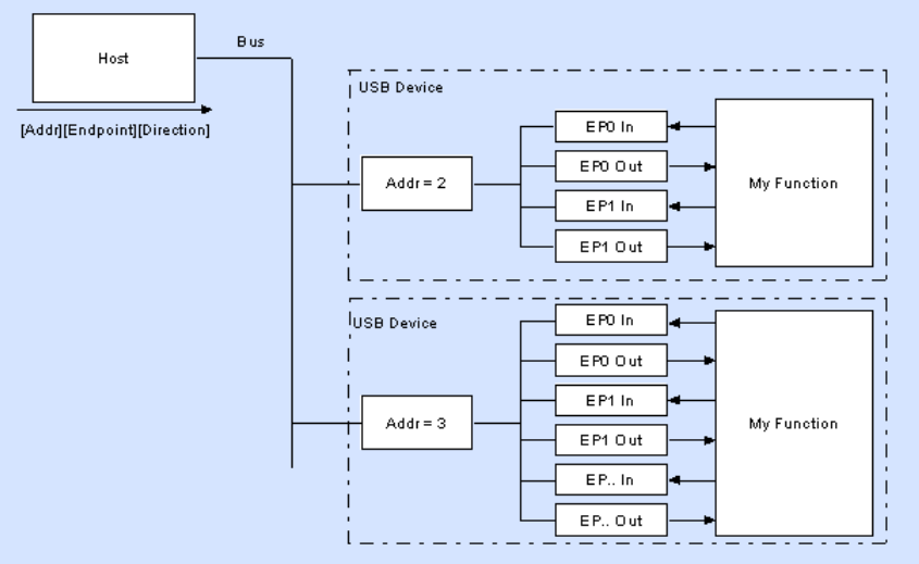
Most functions will have a series of buffers, typically 8 bytes long. Each buffer will belong to an endpoint – EP0 IN, EP0 OUT, etc. Say for example, the host sends a device descriptor request. The function hardware will read the setup packet and determine from the address field whether the packet is for itself, and if so will copy the payload of the following data packet to the appropriate endpoint buffer dictated by the value in the endpoint field of the setup token. It will then send a handshake packet to acknowledge the reception of the byte and generate an internal interrupt within the semiconductor/microcontroller for the appropriate endpoint signaling it has received the packet. This is typically all done in hardware.
The software now gets an interrupt, and should read the contents of the endpoint buffer and parse the device descriptor request.
USB Endpoints
Endpoints can be described as sources or sinks of data. As the bus is host centric, endpoints occur at the end of the communications channel at the USB function. At the software layer, your device driver may send a packet to your devices EP1 for example. As the data is flowing out from the host, it will end up in the EP1 OUT buffer. Your firmware will then at its leisure read this data. If it wants to return data, the function cannot simply write to the bus as the bus is controller by the host. Therefore it writes data to EP1 IN buffer, which sits in the buffer until such time when the host sends a IN packet to that endpoint requesting the data. Endpoints can also be seen as the interface between the hardware of the function device and the firmware running on the function device.
All devices must support endpoint zero. This is the endpoint which receives all of the devices control and status requests during enumeration and throughout the duration while the device is operational on the bus.
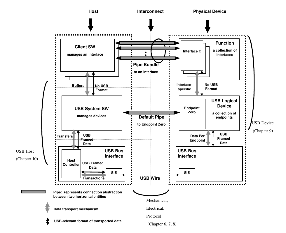
Pipes
A USB pipe is an association between an endpoint on a device and software on the host. Pipes represent the ability to move data between software on the host via a memory buffer and an endpoint on a device.
While the device sends and receives data on a series of endpoints, the client software transfers data through pipes. A pipe is a logical connection between the host and endpoint(s). Pipes will also have a set of parameters associated with them such as how much bandwidth is allocated to it, what transfer type (Control, Bulk, Iso or Interrupt) it uses, a direction of data flow and maximum packet/buffer size. For example the default pipe is a bi-directional pipe made up of EP0 IN and EP0 OUT with a transfer control transfer type.
USB defines 2 types of pipes:
- Stream Pipes have no defined USB format, that is you can send any type of data down a stream pipe and can retrieve the data out the other end. Data flows sequentially and has a pre-defined direction, either in or out. Stream pipes will support bulk, isochronous and interrupt transfer types. Stream pipes can either be controlled by the host or device.
- Message Pipes have a defined USB format. They are host controlled, which are initiated by a request sent from the host. Data is then transferred in the desired direction, dictated by the request. Therefore message pipes allow data to flow in both directions but will only support control transfers.
The USB does not interpret the content of data it delivers through a pipe. Even though a message pipe requires that data be structured according the USB definitions, the content of the data is not interpreted by the USB.
The pipe that consists of the two endpoints with endpoint number zero is called the Default Control Pipe. This pipe is always available once a device is powered and has received a bus reset. Other pipes come into existence when a USB device is configured. The default control pipe is used by the USB System Software to determine device identification and configuration requirements and to configure the device. The Default Control Pipe can also be used by device-specific software after the device is configured.
A software client normally requests data transfers via I/O Request Packets (IRP) to a pipe and then either waits or is notified when they are completed. Details about IRP’s are defined in an operating system-specific manner, e.g. in linux :
usb_sndctrlpipe(dev, 0); // get pipe for endpoint 0 and control transfer
usb_sndbulkpipe(dev, 1); // get pipe for endpoint 1 and bulk transfer
Endpoint types
The Universal Serial Bus Specification defines four transfer/endpoint types:
- Control Transfers
- Interrupt Transfers
- Isochronous Transfers
- Bulk Transfers
Control Transfers
Control data is used by the USB System Software to configure devices when they are first attached. Other driver software can choose to use control transfers in implementation-specific ways. Data delivery is lossless.
Bulk Transfers
Bulk data typically consists of larger amounts of data, such as that used for printers or scanners. Bulk data is sequential. Reliable exchange of data is ensured at the hardware level by using error detection in hardware and invoking a limited number of retries in hardware. Also, the bandwidth taken up by bulk data can vary, depending on other bus activities.
Interrupt transfers
A limited-latency transfer to or from a device is referred to as interrupt data. Such data may be presented for transfer by a device at any time and is delivered by the USB at a rate no lower than is specified by the device.
Interrupt data typically consists of event notification, characters, or coordinates that are organized as one or more bytes. An example of interrupt data is the coordinate from a pointing device. Although an explicit timing rate is not required, interactive data may have response time bounds that USB must support.
Isochronous transfers
Isochronous data is continous and real-time data in creation, delivery and consumption. Timing-related information is implied by the steady state rate at which isochronous data is received or transferred. Isochronous data must be delivered at the rate received to maintain timing. In addition to delivery rate, isochronous data may also be sensitive to delivery delays. A Typical example of isochronous data is voice.
Communication Flow
The USB provides a communication service between software on the host and its USB functions. Functions can have different communication flow requirements for different client-to-function interactions. The USB provides better overall bus utilization by allowing the separation of the different communication flows to a USB function. Each communication flow makes use of some bus access to accomplish communication between client and function. Each communication flow is terminated at an endpoint on a device. Device endpoints are used to identify aspects of each communication flow.